DC Variable Power supply (1.25V To 6.5V)
INTRODUCTION:
A power supply is a circuit which convert Alternating
current (AC) to direct Current (Dc).we supply Dc to all Circuits where we need it.
Dc supply is very important for the proper biasing of a circuit components.with
the help of a variable Dc power supply we give different voltages to a circuit
for biasing because different electronic component works on different voltages.
DEFINITION:
A Dc regulated power supply (with a
variable output voltages from 1.25v to 6.5v) is a circuit which convert
alternating current to variable output direct current.
1.AC SOURCE:
AC is stand for alternating current.AC source is a simple voltage source
which is available in every home .We apply 220v ac to circuit as a input. The
AC source have a sinusoidal wave form.
2.TRANSFORMER:
A transformer is simple an electric device or
also a transformer is an ac machine.There are two types of transformer (1)Step
up transformer and (2)Step down transformer.(1)Step up transformer:
It is the type of transformer which convert low voltage to high voltage.Such type of transformer are use in power houses where the need of high voltage.In step up transformer number of turns in the primary side is less then number of turns in the secondary Np<Ns.(2)Step down transformer:
It also a type of transformer which convert high voltage to low voltage .we use a step down transformer in our circuit it convert 220v AC to 12v AC because we need 12v AC for circuit. In the step down transformer number of turns in the primary side is more than the number of turns in the secondary side Ns>Np.3.RECTIFIER.
Rectifier is a circuit which
convert alternating current to pulsating direct current (DC).There are two
types of rectifier circuit (1) Half wave rectifier and (2) Full wave rectifier
.We use full wave rectifier in our
circuit.
BRIDGE RECTIFIER:
Bridge rectifier is a full wave rectifier.In the bridge rectifier four diodes are use.When the input cycle is positive the diode D1 and D2 are forward biased and conduct the current at this time diode D3 and D4 are reverse biased .When the input cycle is negative the diode D3 and D4 are forward biased and conduct current while diode D1 and D2 are reversed biased.So these process convert alternating current to pulsating direct current.4. FILTER :
A filter is a circuit which covert pulsating dc to a ripple dc.This circuit is connected after the bridge rectifier. In a filter circuit only a capacitor of high value is used . The positive end of a capacitor is connected to the output of a bridge circuit while the negative end is grounded.5. VOLTAGE REGULATOR:
In this circuit we use LM317 voltage regulator .The LM317 voltage regulator has three terminals ,the three terminals are Vout,Vin and ADJUSTMENT (ADJ).The LM317 series regulator are available in standard transistor packages that are easy mounted and handled.The main function of regulator circuit is to convert ripple dc to regulated ripple dc to regulated DC.INTRODUCTION TO BLOCK DIAGRAM:
Block diagram of dc regulated power supply
INTRODUCTION TO THE WORKING PRINCIPAL:
First of all we give
220 v AC supply to a step down transformer convert it to 12.6 v. After this
12.6 v is then passed through bridge
rectifier.The bridge rectifier convert these AC voltages to a pulsating DC
voltages.After the bridge rectifier we connect a filter circuit.The filter
circuit removes pulsation from pulsating DC and give ripple DC voltage.After the ripple part DC
the output of the circuit is passed through voltages regulator circuit which
give the regulated DC output which is our required.
OPERATION:
In the operation of a DC regulated power supply
circuit.First we give 220v AC from the main supply or
main
switch to a step down transformer.the function of step down
transformer
is to convert high voltage to a low voltage. In
the step down transformer the number of primary turns is more than the
number of the secondary turns. The step down transformer give the output
12.6vAC. Then this 12.6v AC are passed through the full wave bridge
rectifier.In the bridge rectifier four diodes are used. The four diodes are (IN4001)
rectifier diodes. When the positive side of the AC voltage into the upper side
of the bridge. The Diode D1 and D3 are forward Biased while D2 and D4 are
reversed Biased and in the next cycle when the Negative cycle comes then the
diodes D1 and D3 are reversed bias while the Diode D2 and D4 are forward
Biased.The Bridge rectifier give the pulsating DC output.After this we connect
a capacitor of value 1000uF. which work as a filter.when the pulsating DC goes
to the peak the capacitor C1 becomes recharge and when the pulsating DC becomes
decrease.At this time the capacitor becomes discharged. Due to this recharging
and discharging of a capacitor.it convert pulsating DC to ripple DC.After this we
connect a voltage regulator. This regulator circuit convert ripple DC to a
regulated DC.Here a three terminal regulator are used which is as adjustable output
controlled by a variable resistor R2. Note that R2 is adjustable from 0 to
1Kohms. The LM317 regulator keeps a constant 1.25v between the output and
adjust terminal.This produce a constant current in R1 of 1.25v/240ohm=52mA.
Neglecting
the very small current through the adjust terminal the current in R2 is the
same as the current in R1.the output is taken across both R1 and R2 and is
found from the Equation.
Vout=1.25v(R1+R2)/R1
Notice
that the output voltage from the power supply is the regulator’s 1.25v
multiplied by the ratio of the resistance.from the case show in the
circuit.when R2 is set to the minimum 0 resistance the output is 1.25v.when R2
is set to the maximum the output is nearly 6.5v.Resistor R1 and R2 is connected
as a voltage divider circuit.Capacitor C2 and C3 is used for more Filtration
output DC.so at the end we get a regulated DC from 1.25v to 6.5v.
CIRCUIT DIAGRAM:
MULTIMETER OUTPUT VOLTAGES:
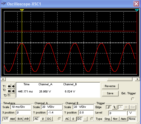
OSCILLOSCOPE INPUT AND OUTPUT WAVEFORM:
ADVANTAGES:
. With the help of dc regulated power we biased all electronic
components.
.With the help of variable dc power supply we apply different voltages to
different component work on different voltages.
USES OF VARIABLE POWER SUPPLY :
.This power supply is used in all
electronic devices.For example .in mobile phone,computers,TV etc.


Gr8
ReplyDeleteHelp me alots in my school project
ReplyDelete