Control LED,s From Infrared (IR) TV Remote Control:
Hello Friends and Welcome to my Blog
In this blog you will be learn how to control different LEDs from infrared
remote control .In my project i am controlling four led,s red, yellow, green and
multi colours .
By pressing the 1 button
on remote control LED red will be turn on
,By pressing button 2 LED red will be turn off ,by pressing 3 led yellow
turn on ,by pressing 4 led yellow turn off ,by pressing 5 led green turn on ,by
pressing 6 led green turn off, by pressing 7 multi colour led turn on and by
pressing 8 it off.
Now if you want to turn on all the leds , just pressing 1,3,5and 7 buttons
with remote control . And if you pressing 2,4,6 and 8 all the leds will be turn
off.
1:Components need for project:
The components that you will be needing for this project are
1:Infrared (IR) sensor Module
2:Infrared (IR)Remote Control
3:Arduino uno (or any other board)
4:LED,s
(red,yellow,green,multicolour)
5:Resistors (4*270ohm) 6:Jumper wires 7:PC/Laptop 8:Breadboard
2: Library:
To use IR sensor you need to
download IR Library. The Library
Link are down given https://github.com/z3t0/Arduino-IRremote .Go to the link download the library unzip it
and change the library name to
IRremote .Copy the library folder and go the to the arduino IDE library
folder and paste it here. Now you can
use IR library in your code.
3:Finding the HEX codes :
First you need to find the hex code for different buttons of IR remote
control, for that you need to copy sketch for finding HEX codes and paste it in arduino IDE .Verify
the sketch and upload it to the arduino board .
Make sure the arduino board are connect to the right port of pc/laptop and also
connect IR reciver module to the arduino board.
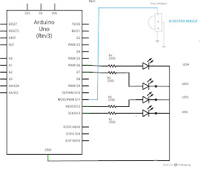
IR sensor module have 3 pins pin 1 which are signal pin connect to the 11
pin of arduino the middle pin VCC are
connected to the 5 volts of
arduino pin and the Ground pin are connected to the ground pin of the arduino.
After upload the sketch go to the serial monitor of Arduino IDE and open it.
Now press one on the IR remote control and you will be seen that HEX code appear on the serial monitor by pressing
different buttons on remote you will be
seen different hex code on serial monitor copy those codes and store it in text file or direct paste it
in your sketch which will be used for controlling leds or for some other
projects.
4:Sketch for finding HEX codes :
#include <IRremote.h>
int RECV_PIN = 11;
IRrecv irrecv(RECV_PIN);
decode_results results;
void setup()
{
Serial.begin(9600);
irrecv.enableIRIn(); // Start the
receiver
}
void loop() {
if (irrecv.decode(&results)) {
Serial.println(results.value,
HEX);
irrecv.resume(); // Receive the
next value
}
delay(100);
}
5:Hex codes:
Small IR remote that come with the sonsor:
1= FFA25D 2=
FF629D 3= FFE21D 4= FF22DD 5=
FF02FD 6= FFC23D 7= FFE01F 8=
FFA857 9= FF906F
0= FF9867 *=
FF6897 #= FFB04F up= FF18E7 down= FF4AB5 left= FF10EF right= FF5AA5 ok=
FF38C7
LED Remote that i am using in my
projects you can use any ir remote:
up=EFC837 down=EF28D7 left=EFA857 right=EF6897 enter=EFE817 valume +=EF08F7 valume -=EFF00F
1=EF807F 2=EF40BF 3=EFC03F 4=EF20DF 5=EFA05F 6=EF609F 7=EFE01F 8=EF10EF
4:Skatch uploading
5:Testing:
6:Sketch for LEDs, Control from
TV infrared (IR)remote control:
#include "IRremote.h"
/*-----( Declare Constants )-----*/
int receiver = 11; // pin 1 of IR receiver to Arduino digital pin 11
/*-----( Declare objects )-----*/
IRrecv irrecv(receiver); // create instance of 'irrecv'
decode_results results; // create instance of 'decode_results'
/*-----( Declare Variables )-----*/
int ledr = 13;
int ledy = 12;
int ledg = 7;
int ledm = 6;
//int fspeed = 100; // fan speed, the defualt speed is 100
void setup() /*----( SETUP: RUNS ONCE )----*/
{
Serial.begin(9600);
Serial.println("IR Receiver Raw Data + Button Decode Test");
irrecv.enableIRIn(); // Start the receiver
pinMode(ledr, OUTPUT);
pinMode(ledy, OUTPUT);
pinMode(ledg, OUTPUT);
pinMode(ledm, OUTPUT);
}/*--(end setup )---*/
void loop() /*----( LOOP: RUNS CONSTANTLY )----*/
{
if (irrecv.decode(&results)) // have we received an IR signal?
{
translateIR();
irrecv.resume(); // receive the next value
}
}/* --(end main loop )-- */
/*-----( Declare User-written Functions )-----*/
void translateIR() // takes action based on IR code received
// describing Car MP3 IR codes
{
switch(results.value)
{
case 0xEF807F:
digitalWrite(ledr, HIGH);
Serial.println("LEDRED ON");
delay(1000);
break;
case 0xEF40BF:
digitalWrite(ledr, LOW);
Serial.println("LEDRED OFF");
delay(1000);
break;
case 0xEFC03F:
digitalWrite(ledy, HIGH);
Serial.println("LEDYellow ON");
delay(1000);
break;
case 0xEF20DF:
digitalWrite(ledy, LOW);
Serial.println("LEDYellow OFF");
delay(1000);
break;
case 0xEFA05F:
digitalWrite(ledg, HIGH);
Serial.println("LEDGreen ON");
delay(1000);
break;
case 0xEF609F:
digitalWrite(ledg, LOW);
Serial.println("LED1 OFF");
delay(1000);
break;
case 0xEFE01F:
digitalWrite(ledm, HIGH);
Serial.println("LEDMulticolour ON");
delay(1000);
break;
case 0xEF10EF:
digitalWrite(ledm, LOW);
Serial.println("LEDMulticolour OFF");
delay(1000);
break;
default:
default:
Serial.println(" other button ");
}
delay(500);
}
7:Circuit daigram :
Fritzing
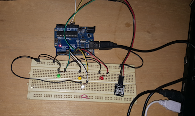
3:Circuit :
As per the circuit Diagram.
For video visit my youtube channel:
https://www.youtube.com/watch?v=fXJeqAAh6Vw&t=170s
Follow me on
? YouTube : https://www.youtube.com/engineeringtube777
? Facebook :https://www.facebook.com/engineeringtube777
? Twitter : https://twitter.com/MohsinH73145168


Nice project thanks for sharing.
ReplyDeleteThanks
DeleteAwesome
ReplyDelete